
Current projects
In this page you will find projects Ralv Holmsen is currently working on, and that are open to the public.
4D Sensor
As technology gets cheaper and more advanced, previously expensive sensors become more available. While there are many different types of 4D sensors, I am currently working on a four dimension sensor by combining cameras and radars. A 4D sensor provides a deeper understanding of the environment than many other detection sensors.
Cameras give a lot of information about a scene, and is especially intuitive to humans. The X/Y (pixel) information as well as information such as color and light intensity means cameras are especially useful at object detection and tracking. What cameras lack however is a sense of depth. While it is possible to use multiple cameras for binocular vision, this kind of depth vision becomes increasingly difficult as the range to the target increases. This is easy to understand intuitively as we humans have to deal with the difficulties of distance estimation on a daily basis, such as when driving a car or doing sports.
Radars usually don't have a lot of X/Y (angle resolution) information as a lot of antennas are required to obtain this information. What radars are good at however is range (Z) and speed (v) measurements, as well as vision through common optical disturbances (clouds, fog, etc). As such radars and cameras complement each other very well, and is especially useful for automation and robotics.
This project is in collaboration with Velociter AS, who among other bring expertise in machine learning and artificial intelligence.

Configuring FPGA on DAC V1 board
DAC Testing
Testing the RF Front end

DAC FPGA Logic

DAC V2
Current activities
Being a rather large project, the task has been somewhat simplified by splitting it into appropriately sized chunks of work. Since camera technology is widely available, cheap, and by no means trivial to make yourself, these image sensors will be bought off the shelf as standard integrated circuits. Radar technology is however not as widely available, with a few new chips available on the market. While the currently available on-a-chip radars are very interesting and impressive, they do lack some of the range I am hoping to achieve with this sensor. Therefore I am working on making such a radar myself.
First and foremost I am making a prototype/proof of concept. My intention is to experiment with different kinds of radar architectures to see which is good enough, scalable, and at a reasonable production cost once optimized. To be able to do this I am building a set of tools to help me with my experiments. Currently this encompass ADCs, DACs, mixers, and analog front-ends.
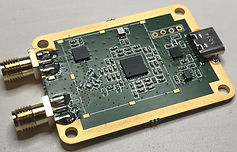
DAC V1
The first iteration of a 14b 400MS/s DAC. The DAC is FPGA based with internal logic featuring a RISC-V processor (with all custom peripherals) to configure and monitor the different systems on board, real-time streaming of data using USB 3.0, internal memory for continuous arbitrary signals, internal NCO with chirp and arbitrary function support, as well as a two times (bypassable) upsampler with hamming over sinc filter (in all modes) through an easy to use python library.
The system as a whole is optimized for a 200MS/s bandwidth with an internal 31 tap hamming over sinc filter as the required bandwidth of the 4D sensor is 84MHz(Legal) /100 MHz(Testing). This bandwidth limitation is also one of USB 3.0 as it it is limited to 5Gb/s and in practice limited to about 2/3 of this. In my system based off a FTDI chip (FT601Q) the actual average data rate is about 350 MB/s (400MB/s bursts), but never lower than 330 MB/s.
The internal logic makes the most out of the USB 3.0 interface, which is just about capable streaming a 200MS/s recording. While this is enough to describe the signal in question, the internal upsampler is intended to increase the bandwidth such that the DAC low pass filter can be relaxed. In addition the data interface is more than adequate when dealing with low bandwidth signals, such as set values for the NCO and chirp functionality.
The system is intentionally limited to support RF circuits. As such, the internal RAM is limited to 32k samples, and the output is optimized for a 1-10dBm unbalanced port, depending on gain settings. The DAC also features internal frequency synthesis to support common RF signals such as FMCW, CW, SFCW, Pulse, and more to come.

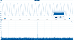
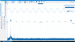
DAC Testing 50 MHz chirp
DAC Testing 99 MHz Sine
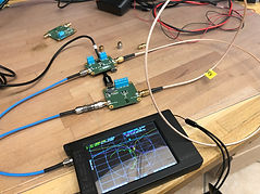
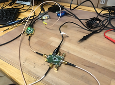
Debugging the DAC (left) with an
oscilloscope and my custom debugger (right)
DAC V2
The second iteration of the DAC system came as the necessity for quadrature signals arose. In addition to having two DACs to cancel out either sideband at RF, it was decided to increase the sample rate even further. The DAC V2 is a 1GS/s 16b dual DAC with integrated up-modulator (mixer) or balanced quadrature output. As the sample rate is so high, it was also decided to simplify the USB interface to high speed (480Mb/s) and instead use a lookup memory which can be updated via USB. The system also allows for low data rate streams if the FPGA is used to synthesize signals, albeit at a lower rate (40 MB/s burst) than the previous iteration.
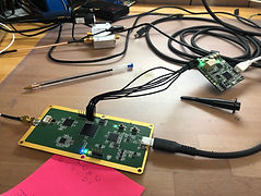
The DAC V2 hardware is currently in testing, but the results are looking promising thus far.
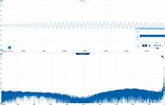
Testing DAC V2 with typical FMCW signal
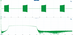


Testing DAC V2 with up-modulation and
downmixing
DAC V2
Local Oscillator
While there are many oscillators available for purchase online, I decided to make my own Local Oscillator (LO). There are a few reasons for this. First and foremost, the majority of the available oscillators online only have a single output. For my test setup I need two identical outputs for some configurations. This is problem is solved by having an RF splitter on the output, which in turn requires buying another tool. Finally, I am integrating an LO in my final design (if not a custom VCO), and getting more experience with LOs is never a bad idea.
The LO features a USB C connector with USB 2.0 full speed interface to an AVR. The AVR monitors and configures the board, and can be accessed via terminal software on any computer. The main oscillator has an integrated VCO and fractional PLL, and is capable of synthesizing frequencies in the frequency domain of interest (among other).
The LO also has a built in Wilkinson splitter using discrete components. The auxiliary (optional) RF output is length matched to the primary output, and is terminated to 50 Ohms if not used.
Local Oscillator
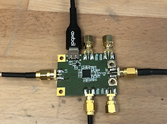
Testing the Local Oscillator using mixers
Result of downmixing the LO during testing
with off the shelf mixers and oscillators
(No filters)
Mixer
Mixing is an important step in radar and radio technology, and its main purpose is to shift signals up or down in the frequency domain. As the mixer is intended for radars, a requirement is that the mixers baseband port can operate at (close to) DC (autocorrelation). Therefore it made sense to go for a quadrature mixer as a quadrature mixer can operate around DC with both negative and positive frequencies. In addition the mixer should be capable of receiving/transmitting from/to source/load as this makes the mixer usable in multiple configurations.
The current mixer supports differential baseband with unbalanced RF and LO components. Perfect for my design, and the quadrature and differential components can always be loaded to make the mixer fully unbalanced and real only (at the cost of some energy).
Quadrature mixer
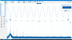
Result of downmixing the LO with my own mixer
during testing (No filters)
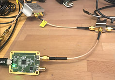
Mixer + LO test setup
Front-End
To get better range the system also needs amplifiers. Delivering the correct amount of output power, as well as the bandwidth and noise figure of the receiver are crucial factors to implement any RF system with good performance. While the maximum output power is limited by law, the receiver chain is arguably the most important aspect of the system to get right. While there are many aspects to receiving strong signals (such as antenna design, etc.) the receiver amplifiers needs a good noise figure, and the input bandwidth must be limited.
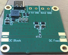
To make things easier for myself, and as the maximum output power is limited, a single amplifier design was made. The amplifier has a decent compression point of around 24 dBm, a gain of roughly 15 dB, and a good noise figure of about 0.8 dB. The amplifier also has input and output filters, where the input bandpass filter is measured to ~2400-2500 MHz. The amplifier also supports power over coax, which is also why I made a DC injection board with a standard USB C connector. The DC injection board inserts 12 VDC.
Receiver/Transmitter amplifier
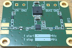
DC injection board for power over coax
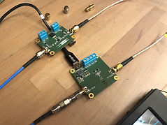
RF amplifier during testing with power over coax